
Alternating current bridge methods are important for measurement of inductance, capacitance, storage factor, dissipation factor etc.The a.c. bridge is natural out growth of Wheatstone Bridge.It's basic form consist of four arms, a source of excitation(ac source), a balance detector.
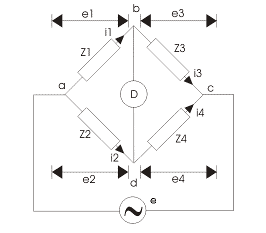 GENERAL EQUATION FOR BRIDGE BALANCE
For balance of bridge the condition required is no current through the detector
i.e. the potential difference between points b and d should be zero. This is possible when, [tex]{e_1} = {e_2}[/tex]
or,[tex]{i_1}{z_1} = {i_2}{z_2}[/tex] ......................(1)
Also at balance,
[tex]{i_1} = {i_3} = \frac{e}{{{z_1} + {z_3}}}[/tex] .......(2)
and [tex]{i_2} = {i_4} = \frac{e}{{{z_2} + {z_4}}}[/tex] ........(3)
substitute eqn.(2) and eqn.(3) gives,
[tex]{z_1}{z_4} = {z_2}{z_3}[/tex]
This is the basic equation for balanced ac bridge.
Consider the polar form, the impedance can be written as,[tex]z = z\angle \theta [/tex]. z represents magnitude and [tex]\theta [/tex]represents the phase angle of the complex impedance.
Hence, [tex]({z_1}\angle {\theta _1})({z_4}\angle {\theta _4}) = ({z_2}\angle {\theta _2})({z_3}\angle {\theta _3})[/tex]
For balance,[tex]{z_1}{z_4}\angle ({\theta _1} + {\theta _4}) = {z_2}{z_3}\angle ({\theta _2} + {\theta _3})[/tex]
MAXWELL'S INDUCTANCE BRIDGE
This bridge is used to measure self-inductance by comparison with a variable standard self-inductance.
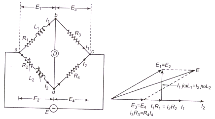
The connection of bridge and phasor diagram for balanced circuit is shown.
Here,
[tex]{L_1}[/tex]= inductance to be measured with resistance [tex]{R_1}[/tex]
[tex]{L_2}[/tex]=variable inductance
[tex]{R_2}[/tex]=variable resistance
[tex]{R_3}[/tex],[tex]{R_4}[/tex]= pure resistance
The balanced condition is that, [tex]{z_1}{z_4} = {z_2}{z_3}[/tex]
or, [tex]({R_1} + j\omega {L_1}){R_4} = ({R_2} + j\omega {L_2}){R_3}[/tex]
Equating real and imaginary part of both sides,
\[\begin{array}{l}
{R_1}{R_4} = {R_2}{R_3}\\
{R_1} = \frac{{{R_2}{R_3}}}{{{R_4}}}
\end{array}\]
and,
\[\begin{array}{l}
{L_1}{R_4} = {L_2}{R_3}\\
{L_1} = \frac{{{L_2}{R_3}}}{{{R_4}}}
\end{array}\]
Hence the unknown resistance can be measured in terms of known inductance and two resistors.And the whole process are independent of frequency. This bridge is used for measurement of iron losses of transformer at audio frequency.
MAXWELL,S INDUCTANCE CAPACITANCE BRIDGE
Here, an inductance is measured by comparison with standard capacitance.
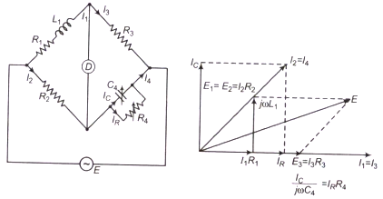
The connection of bridge and phasor diagram for balanced circuit is shown.
Here,
[tex]{L_1}[/tex]= inductance to be measured with resistance [tex]{R_1}[/tex]
[tex]{R_2}[/tex],[tex]{R_3}[/tex],[tex]{R_4}[/tex]= are known pure resistance.
[tex]{C_4}[/tex]=variable standard capacitor.
Now,
\[\begin{array}{l}
{Z_1} = \left( {{R_1} + j\omega {L_1}} \right);\\
{Z_2} = {R_2};\\
{Z_3} = {R_3};\\
{Z_4} = \frac{{{R_4}}}{{1 + j\omega {C_4}{R_4}}}
\end{array}\]
The balanced condition is that,
[tex]{z_1}{z_4} = {z_2}{z_3}[/tex]
\[\begin{array}{l}
\left( {{R_1} + j\omega {L_1}} \right)\left( {\frac{{{R_4}}}{{1 + j\omega {C_4}{R_4}}}} \right) = {R_2}{R_3}\\
{R_1}{R_4} + j\omega {L_1}{R_4} = {R_2}{R_3} + j\omega {R_2}{R_3}{C_4}{R_4}
\end{array}\]
Equating real and imaginary part of both sides,
\[\begin{array}{l}
{R_1} = \frac{{{R_2}{R_3}}}{{{R_4}}}\\
{L_1} = {R_2}{R_3}{C_4}
\end{array}\]
Expression for Q factor, [tex]Q = \frac{{\omega {L_1}}}{{{R_1}}} = \omega {C_4}{R_4}[/tex]
HAY'S BRIDGE
Hay's bridge is a modification of Maxwell's bridge with a series resistance connected to standard capacitor, instead of resistance parallel with capacitor.
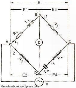
Let,
[tex]{L_1}[/tex]= inductance to be measured with resistance [tex]{R_1}[/tex]
[tex]{R_2}[/tex],[tex]{R_3}[/tex],[tex]{R_4}[/tex]= are known pure resistance.
[tex]{C_4}[/tex]= Standard capacitor.
Now,
\[\begin{array}{l}
{Z_1} = {R_1} + j\omega {L_1};\\
{Z_2} = {R_2};\\
{Z_3} = {R_3};\\
{Z_4} = {R_4} - \frac{j}{{\omega {C_4}}}
\end{array}\]
The balanced condition is that,
[tex]{z_1}{z_4} = {z_2}{z_3}[/tex]
or,[tex]({R_1} + j\omega {L_1})\left( {{R_4} - \frac{j}{{\omega {C_4}}}} \right) = {R_2}{R_3}[/tex]
Separating real and imaginary terms,we get,
\[\begin{array}{l}
{R_1}{R_4} + \frac{{{L_1}}}{{{C_4}}} = {R_2}{R_3}\\
{L_1} = \frac{{{R_1}}}{{{\omega ^2}{R_4}{C_4}}}
\end{array}\]
Solving these simultaneous equations we get,
\[\begin{array}{l}
{R_1} = \frac{{{\omega ^2}{R_2}{R_3}{R_4}C_4^2}}{{1 + {\omega ^2}R_4^2C_4^2}}\\
{L_1} = \frac{{{R_2}{R_3}{C_4}}}{{1 + {\omega ^2}R_4^2C_4^2}}
\end{array}\]
The expressions contain the frequency term which is same as the frequency of source of supply.
Hence for calculation of unknown inductance we should know the frequency of supply.
ANDERSON'S BRIDGE
This bridge is modification of the maxwell's inductance capacitance bridge. Here self inductance is measured in terms of standard capacitor over a wide range of values.
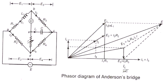
[tex]{L_1}[/tex]= the self-inductance to be measured
[tex]{R_1}[/tex]=resistance connected in series with self-inductor
[tex]{r}[/tex],[tex]{R_2}[/tex],[tex]{R_3}[/tex],[tex]{R_4}[/tex]= are known pure resistance.
C= fixed standard capacitor.
Comments

DanielHeller
Fri, 05/18/2018 - 11:21
Awesome, Thanks for contributing your important time to post such an interesting & useful collection of knowledgeable resources that are always of great need to everyone. I visit this blog first time and encourage by this good stuff work. Unbelievable post keeps up posting such great information. custom essay writing service There are things here that I didn't think some time as of late. am very enjoyed for this weblog. It’s an informative subject matter.